Millivolt/microvolt voltage amplifier signal amplifier AD623/AD620 instrumentation amplifier module
AD623/AD620 Instrumentation Amplifier Module
product description:
Dedicated instrumentation amplifier core, rail-to-rail output, high input impedance, high common-mode rejection ratio, low offset and drift, low noise, high closed-loop gain stability, and precision measurement/amplification.
Module characteristics
1. High-end dedicated instrumentation amplifier AD623 core with high precision and good linearity.
2. Single power supply, support 3-5.5V power supply, easy to use!
3. Integrated negative pressure generating module, dual power supply operation, easy to deal with negative signal / AC signal.
4. Power input LC filtering, pure and stable, to ensure the stability of signal amplification.
5. Built-in negative voltage generating module, only need a single power supply to operate with dual power supply, simplifying system design.
6. Rail-to-rail output, the maximum output swing is +-VCC, far beyond the core products such as LM358/AD620 (only to VCC-1.5V)
7. Magnification 2-1000 times adjustable, adapt to different applications, imported US bounds potentiometer, uniform resistance change, stable resistance, the price is higher than domestic potentiometer 10 times or more (inferior potentiometer often loose, open, beat, When the resistance is large, small, open, etc., it is impossible to ensure that the amplification factor is stable, and it is difficult to ensure accuracy.
7. The module is simple, expandable, and detailed, convenient for secondary development.
The main parameters
Amplifier Type: Dedicated Instrumentation Amplifier AD623 Core
Input range: 0.5VCC (ie, the voltage between S+/S- is less than half of the supply voltage.)
Output range: +-VCC (rail to rail)
Magnification: 2-1000 times adjustable.
Power consumption: 150uA (typical) 650uA (maximum)
Power supply: 3-5.5V
Gain accuracy: 0.35% (G> 2) 0.10% (G = 2)
Input offset voltage: 100-200uV
Input offset drift: 1uv/°C
Common mode rejection ratio: 90db
Gain bandwidth: 800KHZ.
PCB size: 40*23mm
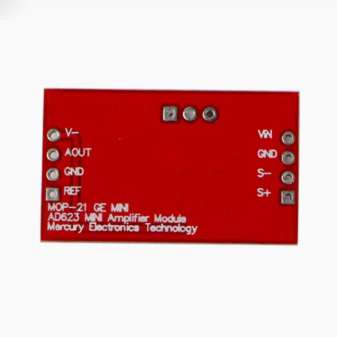
Pin description and wiring diagram
It is recommended to test the baby with a smaller magnification (eg 50/100 times) and then adjust to the desired multiple. Adjusting the A++ knob clockwise increases the magnification (up to 1000 times). When it is adjusted to the maximum, you can hear a slight click from the potentiometer, indicating that it has been adjusted to the end. It is also possible to use a resistor to fix the magnification so that the amplification value will be more stable.
MV ad623/ad620 instrument amplifier module
Product Description:
Special instrument amplifier core, rail to rail output, high input impedance, high common mode rejection ratio, low offset and drift, low noise, and high closed-loop gain stability, the best choice for precision measurement / amplification.
Module features
1. High end special instrument amplifier AD623 core, high precision and good linearity.
2. Single power supply, support 3-5.5v power supply, easy to use!
3. Integrated negative pressure generation module, dual power supply operation, easy to deal with negative signal / AC signal.
4. The power input LC filter is pure and stable to ensure the stability of signal amplification.
5. The built-in negative voltage generation module can operate with dual power supplies only with a single power supply, simplifying the system design.
6. Rail to rail output, with an output swing of +-vcc, far exceeding core products such as lm358/ad620 (only vcc-1.5v)
7. The amplification factor is adjustable from 2 to 1000 times, which is suitable for different applications. The imported American bounds potentiometer has uniform resistance change and stable resistance value, and the price is more than 10 times higher than the domestic potentiometer (the poor potentiometer is often loose, open circuit, jumping, causing the resistance to be large and small, open circuit, etc., which cannot ensure the stability of amplification factor, and it is difficult to ensure the accuracy).
7. The module is simple, expandable, detailed and accurate, and convenient for secondary development.
main parameter
Amplifier type: special instrument amplifier AD623 core
Input range: 0.5Vcc (that is, the voltage between s+/s- is less than half of the power supply voltage.)
Output range: +-vcc (rail to rail)
Magnification: 2-1000 times adjustable.
Power consumption: 150ua (typical) 650ua ()
Power supply: 3-5.5v
Gain accuracy: 0.35% (g>2) 0.10% (g=2)
Input offset voltage: 100-200uv
Input offset drift: 1uv/ ℃
Common mode rejection ratio: 90dB
Gain bandwidth: 800KHz.
PCB size: 40*23mm
Pin description and wiring diagram
It is recommended to use a smaller magnification (such as 50/100 times) to test the baby, and then adjust it to the required magnification. Adjust the a++ knob clockwise to increase the magnification (1000 times). When it is adjusted, you can hear a slight click of the potentiometer, which means that it has been adjusted to the end. Resistance can also be used to fix the magnification, so that the amplification value will be more stable
matters needing attention
1. Some people call ref as the zero pin, which is no problem, but the accuracy of AD623 core is very high. Directly grounding ref, the output is very close to 0, and there is no need to adjust it in practice. It is recommended to adjust the ref pin voltage only when it is necessary to shift the voltage
2. Our store uses imported American bounds potentiometers, which have uniform and stable adjustment and high reliability. The price is 10 times higher than that of domestic potentiometers, which is comparable to non ordinary domestic potentiometers.
3. The offset voltage of AD623 is 200uv, which may produce an error of 200uv on the input voltage. Therefore, if the input voltage is smaller, the initial error is larger. It is recommended that the signal should not be lower than 3MV.
4. The 3dB gain bandwidth of AD623 is 800KHz, that is, gain multiple * frequency =800khz. Therefore, if the DC signal is amplified, it can reach about 1000 times. If the amplification is 800 times, the signal should not be higher than 1kHz. If the amplification is 10 times, the signal should not be higher than 80kHz, and so on. The higher the signal frequency, the greater the amplification loss.
5. The adjustment range of ref end should not be too large, otherwise the magnification will be affected.
6. The output voltage range of the amplifier is restricted by the power supply voltage. The linear area of AD623 module in our store is up to +-vcc. When ad620/lm358 and other amplifiers are powered by +5v and -5v, the linearity is only between -3.6v and + 3.6V.
7. The ref pin of AD623 can only pull up / down the output voltage. Generally, it is grounded. When you need to use the ref pin to pull up or down the output, you can change the voltage of this pin. However, in this case, it should be noted that the linear region of the magnification will not change due to the change of 5 pins, and its output will not exceed VCC.
General knowledge of instrument amplifier
Various non electric quantity measurements are usually converted into voltage (or current) signals by sensors, which are generally weak, ranging from 0.1 μ 5. Moreover, the dynamic range is wide, and there is often a large common mode interference voltage. Therefore, the instrument amplifier is usually connected behind the sensor, which is mainly used to accurately amplify the voltage of the sensor signal and suppress the common mode interference signal, so as to improve the quality of the signal.
In the application of general signal amplification, the differential amplification circuit is usually required to amplify the signal and then collect it. However, the basic differential amplification circuit has poor precision, and the resistance matching problem is the main factor affecting the common mode rejection ratio. If the discrete operational amplifier is used as the measuring circuit, it is inevitable that there will be resistance differences, and the variables affecting the amplification of the whole signal will be more complex, resulting in the reduction of common mode rejection ratio and the nonlinearity of gain. The integrated instrument amplifier made by the post mold process solves the above matching problem, while the instrument amplifier circuit does not have the above shortcomings, so it is widely used.
Because the output impedance of the sensor is generally very high, the output voltage amplitude is very small, and the working environment is bad, the instrument amplifier has special requirements compared with the general-purpose amplifier, mainly manifested in high input impedance, high common mode rejection ratio, low offset and drift, low noise, and high closed-loop gain stability.
General integrated instrument amplifiers have the following characteristics
(1) The input impedance is high, generally higher than 109 Ω
(2) Low bias current
(3) High common mode rejection ratio
(4) Balanced differential input
(5) Good temperature characteristics
(6) Gain adjustable
(7) Single ended input
Hot ProductsNew Products For July


Recently ViewedRelated Product


|