1.1 The two digit digital tube is used to display the sampling current value, and the results of chip sampling calculation are displayed on the two digit digital tube for direct reading
1.2 Easy to use
Power the module normally, and then connect it to the circuit under test
1.3 Practical and powerful
Under the environment of - 40~85 ℃, the current monitor can accurately monitor the current of 0~30A. The measurement conditions are simple and easy to use. The external standard input voltage is provided and then compared with the current sampling module to determine whether the current detected by the current monitor is within the allowable range. If the collected value exceeds the measurement range, the current monitor will send out a prompt signal.
1.4 Convenient for later development
The serial output port of the current monitor can continuously output sampling data, which is convenient for secondary development.
2.1 Digital tube
Two digit nixie tubes are used to display the current value.
2.2 Compare Output Ports
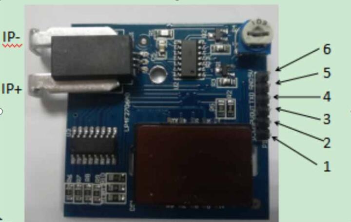
As shown in Figure 1, pin 1 is the external input port connected to the external reference voltage.
2.3 Compare output ports
As shown in Figure 1, pin 2 is the comparison output port. By comparing the external reference voltage and the voltage of the sampling current module, we can determine whether the current we collect is out of range. If the range is exceeded, pin 2 will output a high level, which can be used as an alarm signal.
2.4 Serial port output
As shown in Figure 1, pin 4 is a serial output port.
2.5 Power port
As shown in Figure 1, pin 5 is GND and pin 6 is+5V input.
2.6 Current sampling port
As shown in Figure 1, the IP+port near the edge of the circuit board is the current sampling input port, and the IP - port is the current sampling output port.
3 Getting Started
3.1 Power on
Connect the DC+5V voltage to the power port of the current monitor and wait for about 0.5 seconds.
3.2 External standard input
To determine whether the current we detect is within our allowable range, we can input the reference voltage through the external comparison input port. The amplitude current equation corresponding to the reference voltage is: Uc=2.5+Ic * k. (When the input voltage is 5V, the sampling current module coefficient k is 26Mv/A
3.3 Start to detect current
Connect the sampling port of the current monitor to the current circuit to be tested in series.
3.4 Digital tube display and serial port output
The current sampling data can be read from the nixie tube and the serial port. The serial port baud rate is 9600bps. The protocol for sending the data frame is: two bytes per frame of the data frame. The BCD code corresponds to the high four bits. The first byte represents the positive and negative data, where A represents a positive number and B represents a negative number. The BCD code corresponds to the low four bits of the first byte and the high four bits of the second byte are used to represent the integer of the current value, The BCD code of the lower four bits of the second byte represents the decimal digits of the current current value.
4 Product specifications
4.1 Product version
Current sampling core board v1.0
4.2 Power input
+5V
4.3 Power consumption
<30mA
4.4 Hall coefficient of current sampling
22.6mV/ A
4.5 Dimensions
(L x W x H) 45mm x 45mm x 1.6m
Hot ProductsNew Products For July


Recently ViewedRelated Product


|